Strengthening Mechanisms
On this page, we will learn about the four main mechanisms to strengthen crystalline materials that have dislocations. Start with an exploration of one in Exercise 12.9.1 and then learn about other mechanisms below.
1. Solid-Solution Strengthening (Impurities)
Many materials are quite weak in their pure form due to dislocations. One method for strengthening materials is by adding impurities which impede dislocation motion. This is known as solid-solution strengthening and it is what we explored in Exercise 12.9.1. A solid solution, as discussed in Section 10.3.2, is a solid of one type with atoms of another type "dissolved" in it, i.e., it is a solid with impurity atoms. In NetLogo model 12.9.1 we edited the sizes of atoms to model substitutional impurity atoms. A solid solution can also be made a of a host lattice with interstitial atoms and these can also hamper dislocation movement. Both options are illustrated in Figure 12.9.1.
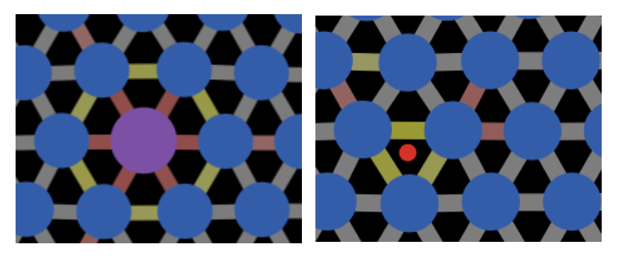
Figure 12.9.1 Both substitutional impurities (left) and interstitial impurities (right) can cause bonds to be stretched and compressed in the lattice. These can counteract the compressive and tensile strain from a dislocation, making it harder for the dislocation to move.
High purity metals are typically softer than their alloys for this reason. There are many common examples of metals that are strengthened by adding impurities. For example:
- The most basic type of steel is iron with carbon interstitial impurities added.
- Pure gold is extremely soft. So, gold used for jewelery is alloyed with some combination of silver, copper, nickel, and zinc.
It is important to realize, that a solid solution can strengthen a material even when you add atoms from a weaker material! This is shown in Figure 12.9.2. Copper and nickel form a complete solid solution (Figure 10.6.1). Even though pure copper is weaker than pure nickel, an alloy of the two is still stronger than pure nickel because the copper impurities block dislocations.
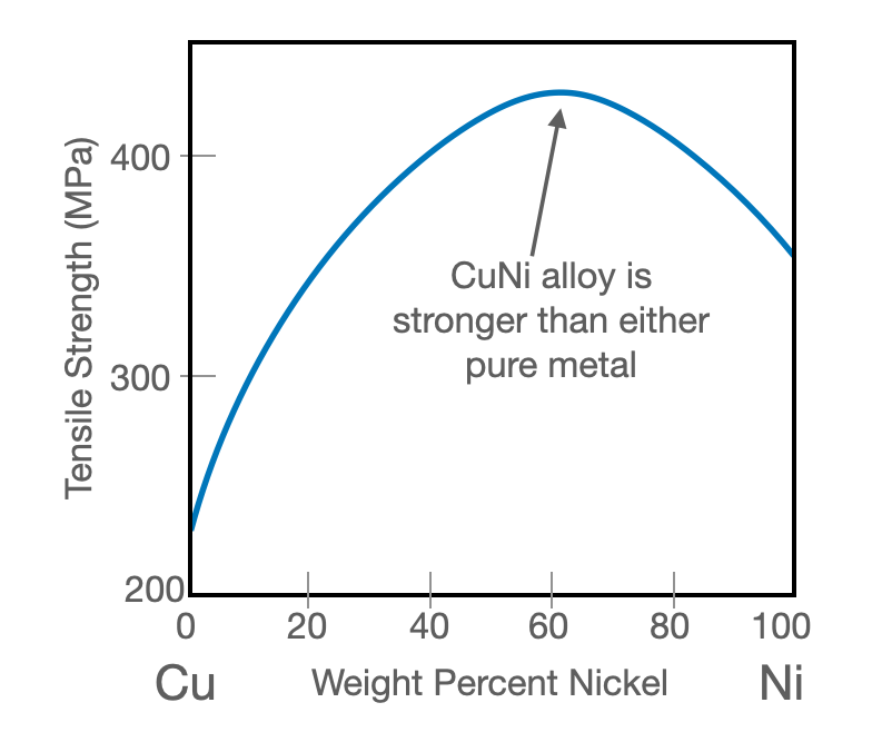
Figure 12.9.2 Tensile strength of copper-nickel alloy as a function of weight percent nickel. Even though pure nickel is stronger than pure copper, adding copper to nickel still strengthens it, because the impurities block dislocations.
2. Precipitate Hardening
As discussed in Chapter 10, it is possible to have two different solid phases coexisting in a single solid. When one of the phases comprises most of the volume, we call the small volume phase a "precipitate." This is different from solid-solution hardening discussed above in which there is only one phase with some impurities present. In precipitate hardening, there are at least two phases present in the solid creating a microstructure. The precipitates act as blockades for dislocation motion, hardening the material.
Many types of aluminum used in the automotive and aerospace industries use precipitate hardened aluminum. Figure 12.9.3 shows a microscope image of a precipitate hardened aluminum in which precipitates are visible as black dots.
 is aluminum containing magnesium and silicon as major alloying components (as well as small amounts of other elements). $\ce{Mg2Si}$ precipitates, visible as black dots in this image ([image source](https://commons.wikimedia.org/wiki/File:6061_Aluminum_Grain_Boundaries.png)).](https://mmedium-django-static.s3.amazonaws.com/media/images/6061_Aluminum_Grain_Boundaries.png)
Figure 12.9.3 6061 aluminum alloy is aluminum containing magnesium and silicon as major alloying components (as well as small amounts of other elements). $\ce{Mg2Si}$ precipitates, visible as black dots in this image (image source).
3. Grain Size Reduction
In the vast majority of macroscopic crystalline materials, the material is not a single crystal. Instead it is made up of many "grains" (also called "crystallites"). All the grains have the same crystal structure, but they are rotated so they don't line up. Figure 12.9.4 shows a schematic of grains at the atomic level on the left and a micrograph of grain boundaries in a real alloy on the right.
). With proper preparation, called "etching", grain boundaries can be seen under a microscope.](https://mmedium-django-static.s3.amazonaws.com/media/images/grain_boundaries.png)
Figure 12.9.4 Left: a schematic of grain boundaries at the atomic level. All the grains have a simple cubic lattice, but they are rotated relative to one another. At the grain boundaries, the lattice gets distorted. Right: A micrograph of grains in a metal alloy (file source). With proper preparation, called "etching", grain boundaries can be seen under a microscope.
Grain boundaries disrupt dislocation motion because they cause a discontinuity in the slip plane. For the dislocation to traverse from the slip plane in one grain to that in another requires extra energy/force.
When the angle between the grains is large, dislocations my fail to traverse from one grain to the other and they can "pile up" at the grain boundaries. These introduce stress in the lattice which can cause brittleness and can also generate new dislocations in neighboring grains.
Finally, we can explain why decreasing grain size strengthens materials: if the grains in a material are smaller, there are more grain boundaries. More grain boundaries means more barriers for dislocations.
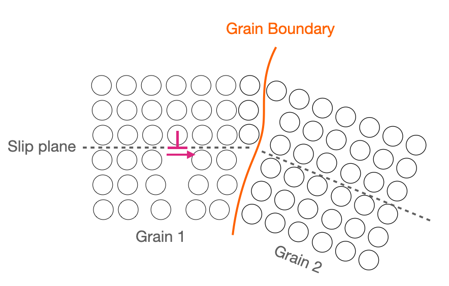
Figure 12.9.5 A grain boundary causes a discontinuity in slip planes, hindering dislocation motion.
4. Strain Hardening
The last main mechanism for strengthening metals is seemingly paradoxical: adding more dislocations! If you plastically deform a piece of metal, it will become harder (or stronger - the two properties are closely related). This is because the deformation introduces new dislocations. This might seem strange at first, because dislocations are the reason that metals are much weaker than perfect crystals, as we saw in our simulations. So, it turns out that a very low density of dislocations a material is weaker compared to zero dislocations, but after a certain density $\rho_{c}$ is reached, adding more dislocations strengthens the materials again, as shown in Figure 12.9.6. Why is this?
 which in turn cites [É M Nadgornyĭ 1962 Sov. Phys. Usp. 5 462](https://iopscience.iop.org/article/10.1070/PU1962v005n03ABEH003433/meta)](https://mmedium-django-static.s3.amazonaws.com/media/images/dislocations_vs_yield_strength.svg)
Figure 12.9.6 A stylized graph of yield strength vs dislocation density. The ideal strength would be achieved with zero dislocations. Real nanowires can approach this strength. As dislocation density increases from zero, yield strength decreases to a minimum at a critical density of dislocations, $\rho_c$. Bulk metals typically have at least this density of dislocations. Increasing dislocation density beyond this point strengthens the materials.
Graph based on G I Kanel et al 2017 Phys.-Usp. 60 490 which in turn cites É M Nadgornyĭ 1962 Sov. Phys. Usp. 5 462
The reason increasing dislocation density beyond $\rho_c$ strengthens the material is that dislocations interact with each other. Two dislocations of opposite sign (which can be quantified with the Burger's vector (Section 12.8), will cause opposite strains on the lattice. This will cause them to attract one another and annihilate. A simulation of this is shown in Video 12.9.1. On the other hand, two dislocations of the same sign will repel each other. It turns out, that when you have a lot of dislocations, the average interaction is repulsive, making it harder for dislocations to move.
Video 12.9.1
The main way to introduce more dislocations into a material is through strain hardening, also known as cold working. For this reason, strain hardening is also frequently called cold working or work hardening. In this process, a material is stretched or bent into the plastic regime (permanent deformation) which creates more dislocations. These usually make the material stronger, but also more brittle. The dislocations do not change the nature of the bonding in the material, so work hardening has little effect on the elastic modulus.